English
Sign in
| Price | $300 to $2000 |
| MOQ | 1 |
| Delivery Time | 7 work days |
| Brand | NUOYINGJIAYE |
| Place of Origin | China |
| Certification | Explosion-proof certificate |
| Model Number | NYLD |
| Packaging Details | Export standard packing |
| Payment Terms | T/T |
| Supply Ability | 300 pcs/ pre month |
| Nominal Diameter(mm) and Connection method | 4,6,10,15,20,25,32,40 (tread connection) 15,20,25,32,40 (tread and flange connection) 50,65,80,100,125,150,200 ( flange connection) | Place of Origin | China |
| Packaging Details | Export standard packing | Accuracy Class | Regular accuracy ±1%R, ±0.5%R, Highest accuracy ±0.2% R |
| Model Number | NYLD | Ambient Conditions | Temperature:-10~+55℃, Relative Humidity: 5%~90% Atmosphere Pressure:86~106Kpa |
| Instrument material | 304 stainless steel; 316L stainless steel; etc. | Supply Ability | 300 pcs/ pre month |
| Certification | Explosion-proof certificate | Brand Name | NUOYINGJIAYE |
| Payment Terms | T/T | Protection Class | IP65 |
| Measurement Range Rate | 1:10,1:15,1:20 | Price | $300 to $2000 |
| Delivery Time | 7 work days | Explode-proof Class | ExdIIBT6 |
| Minimum Order Quantity | 1 | Signal Transmission Line | STVPV 3×0.3 (three wires), 2×0.3(two wires) |
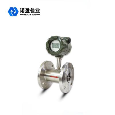
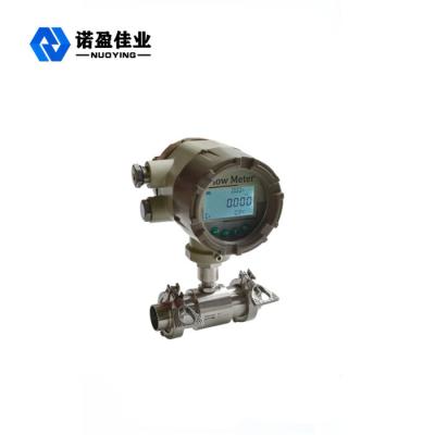
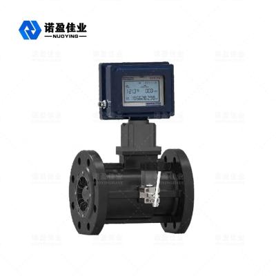
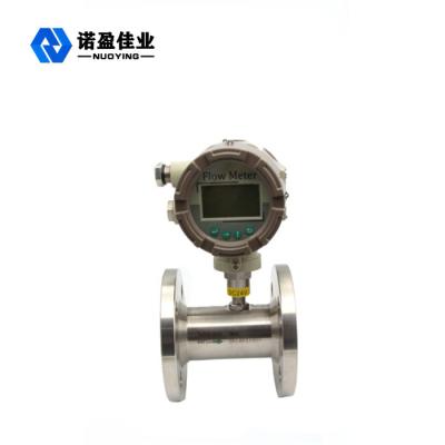
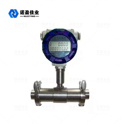
NYLD Turbine Flowmeter
The
NYLD turbine
flowmeter
(Abbr.
TUF)
is
a
main
type
of
Impeller
Flowmeters
also
including
the
Anemoscope
and
Water
meter.
TUF
is
made
up
of
Sensor
and
Conversion-Show.
The
Sensor
reacts
to
the
average
velocity
of
fluid
with
multi-blades
rotor
so
as
to
speculating
the
flow
value
and
the
accumulative
flow
value.
The
velocity
(or
circles)
of
rotor
can
be
picked
up
by
the
way
of
mechanism,
electromagnetic
induction,
photoelectricity,
before
displaying
and
transmitting
the
records
by
reading
device.
It
is
said
that
America
announced
the
first
TUF
patent
early
in
1886.
The
patent
in
1914
recorded
that
the
TUF
flow
value
is
relevant
to
frequency.
The
first
developed
TUF
in
1938
is
applied
to
measuring
the
fuel
flow
in
the
aircraft.
It
is
eventurelly
achieved
to
use
in
the
industry
until
the
end
of
the
world
war
two,
since
it
is
urgent
for
the
jet
engine
and
liquid
jet
fuel
to
demand
high
accuracy,
quick
responses
flow
measurement
instrument.
Nowadays,
it
can
be
extensively
used
in
the
fields
of
oil,chemical,defence,science,measuring,
etc..
NYLD
series
Turbine
Flowmeters
draw
the
leading
technology
integrating
with
advanced
design
to
produce
the
new
generation
of
turbine
flowmeter
with
the
features
of
simple
structure,
light
weight,
high
accuracy,
good
repeatability,
flexible
reaction,
convenient
installation/maintenance/application
etc..
It
is
widely
applied
to
measuring
the
liquid
of
which
kinematic
viscosity
is
under
5*10-6㎡/s
and
have
no
impurify
of
fibre,grain
etc.,and
no
corrosive
interaction
with
the
stainless
steel
1Cr18Ni9Ti,2Cr13,and
A12O3,
and
hard
alloy
in
seal
pipes.
The
liquid
of
kinematic
above
5*10-6㎡/s
can
be
measured
after
real
liquid
calibration
of
flowmeter.
It
can
be
used
in
value
control,
siren
when
excess,
if
co-ordination
with
special
display
instrument.
So
it
is
the
ideal
instrument
of
measuring
flow
value
and
saving
energy.
NYLD Turbine Flowmeter Basic Parameters / Technical Specification
Technical Specification
|
Nominal Diameter(mm) and Connection method |
4,6,10,15,20,25,32,40 (tread connection) 15,20,25,32,40 (tread and flange connection) 50,65,80,100,125,150,200 ( flange connection) |
| Accuracy Class |
Regular accuracy ±1%R, ±0.5%R, Highest accuracy ±0.2% R |
| Measurement Range Rate | 1:10,1:15,1:20 |
| Instrument material | 304 stainless steel; 316L stainless steel; etc. |
| Medium Temperature(℃) | -20 ~ +120 ℃ |
| Ambient Conditions |
Temperature:-10~+55℃, Relative Humidity: 5%~90% Atmosphere Pressure:86~106Kpa |
| Signal Output |
Sensor: pulse frequency signal, low level≤0.8V high level≥8V. Transmitter: current signal 4~20mA DC two wires |
| Supply Power |
Sensor: +12V DC, +24V DC (option) Transducer: +24V DC Scene display type meter: 3.2V Lithium cell |
| Signal Transmission Line | STVPV 3×0.3 (three wires), 2×0.3(two wires) |
| Transmission Distance | ≤1000m |
| Signal Line Interface | Internal thread M20×1.5 |
| Explode-proof Class | ExdIIBT6 |
| Protection Class | IP65 |
Measurement range and Working pressure for liquid
|
Nominal Diameter (mm) |
Regular Flow rate (m3/h) |
Expanding flow rate (m3/h) |
Regular tolerance pressure(Mpa) |
Special tolerance pressure(Mpa) (flange connection) |
| DN4 | 0.04—0.25 | 0.04—0.4 | 6.3 | 12, 16, 25 |
| DN6 | 0.1—0.6 | 0.06—0.6 | 6.3 | 12, 16, 25 |
| DN10 | 0.2—1.2 | 0.15—1.5 | 6.3 | 12, 16, 25 |
| DN15 | 0.6—6 | 0.4—8 | 6.3, 2.5(flange) | 4.0, 6.3, 12, 16, 25 |
| DN20 | 0.8—8 | 0.45—9 | 6.3, 2.5(flange) | 4.0, 6.3, 12, 16, 25 |
| DN25 | 1—10 | 0.5—10 | 6.3, 2.5(flange) | 4.0, 6.3, 12, 16, 25 |
| DN32 | 1.5—15 | 0.8—15 | 6.3, 2.5(flange) | 4.0, 6.3, 12, 16, 25 |
| DN40 | 2—20 | 1—20 | 6.3, 2.5(flange) | 4.0, 6.3, 12, 16, 25 |
| DN50 | 4—40 | 2—40 | 2.5 | 4.0, 6.3, 12, 16, 25 |
| DN65 | 7—70 | 4—70 | 2.5 | 4.0, 6.3, 12, 16, 25 |
| DN80 | 10—100 | 5—100 | 2.5 | 4.0, 6.3, 12, 16, 25 |
| DN100 | 20—200 | 10—200 | 2.5 | 4.0, 6.3, 12, 16, 25 |
| DN125 | 25—250 | 13—250 | 1.6 | 2.5, 4.0, 6.3, 12, 16 |
| DN150 | 30—300 | 15—300 | 1.6 | 2.5, 4.0, 6.3, 12, 16 |
| DN200 | 80--800 | 40—800 | 1.6 | 2.5, 4.0, 6.3, 12, 16 |
Measurement range and Working pressure for gas
| Model |
Diameter (mm) |
Flow Rate (m3/h) |
Initial Flow Rate (m3/h) |
Tolerance pressure(Mpa) (flange connection) |
| 25A |
25 (1”)
|
0.7—7 | 0.6 | 4.0 Flange or Thread |
| 25B | 1.5—15 | 1.0 | 4.0 Flange or Thread | |
| 25C | 3—30 | 2.0 | 4.0 Flange or Thread | |
| 40A | 40 (1.5”) | 4—40 | 2.5 | 4.0 Flange or Thread |
| 40B | 8—80 | 3 | 4.0 Flange or Thread | |
| 50A | 50 (2”) | 10—100 | 3.5 | 4.0 Flange |
| 50B | 15—150 | 4 | 4.0 Flange | |
| 80 | 80 (3”) | 15—300 | 4 | 1.6 Flange |
| 100 | 100 (4”) | 20—400 | 5 | 1.6 Flange |
| 150 | 150 (6”) | 50—1000 | 8 | 1.6 Flange |
| 200 | 200 (8”) | 100—2000 | 20 | 1.6 Flange |
| 250 | 250 (10”) | 150—3000 | 30 | 1.6 Flange |
| 300 | 300 (12”) | 200—4000 | 40 | 1.6 Flange |
NYLD Turbine Flowmeter Operating Principle
As the measured liquid flows through the sensor, the drived vane begins to turn, which velocity is in direct proportion to average flow one in the pipe. The turn of vane periodically changes the magnetic resistance value of magnetoelastic transducer. Magnetic flux in the magnetic test coil happens to change cyclically with it to produce periodic induced voltage, it is the pulse signal, that will be sent to the display to show after amplified by magnifier.
Flow rate equation of Turbine Flowmeter includes both practical and theoretical one:
Qv=f/k
Qm= Qv vρ
Qv refers to volume flow rate, (unit: m3/s)
Qm refers to mass flow rate, (unit ㎏/s)
f : refer to output signal frequency (unit Hz)
k : refer to the Flowmeter factor, (unit P/m3).
The related curve of flowmeter factor and flow rate is in the graph (Diagram: Turbine flowmeter characteristic curve). As your seeing, the factor curve can be divided into two parts of linearity and non-linearity. The linear part accounts for two-thirds of the entire curve which feature is related to the structure, size of sensors, and fluid viscosity. The feature in non-linearity part is influenced by friction force from bearing, the viscosity resistance of liquid. When flow rate is below the lower limit of sensor, the instrument factor are quickly increasing with it. The value of pressure loss and the flow rate are similar to be square relations. If flow rate surpassed the upper limit, pay attention to preventing from cavitation. When the turbine flowmeters have similar structure, their curves have similar feature but have different system errors.

The sensor factor can be worked out by calibration instrument, which may have no consideration of the sensor’s inside fluid mechanism, and can be confirmed by inputed flow rate and outputed pulse signals of frequency. So we can see the sensor as a black box , that is convenient for application. But please note that the conversion factor (or instrument factor) should comply with some conditions which calibration condition is the reference condition . If it deviate from this condition, the factor will happen to change. The changes would be determined in terms of the sensors type, the pipe installation condition,and fluid physical parameters.
According moment of momentum theorem can list the equation of motion impeller.
J dw dt =M1-M2-M3-M4
In the formula,
J: impeller inertia moment;
dw dt: rotational acceleration;
M1 : Liquid-driven torque
M2 : Viscous resistance moment
M3 : Bearing friction moment
M4 : Magnetic moment.
When impeller is rotating according to constant velocity, J dw dt =0, and M1=M2+M3+M4. Through the analysis in theory and verification in experiment ,the formula can be deduced that is:
n=Aqv+B- C qv
In the formula,
n: refers to impeller rotational speed;
qv: refers to volume flow rate;
A: the factors related to fluid physical properties ( include density, viscosity etc.), impeller structure parameters (blade angle, impeller diameter, flow channel cross-sectional area etc.);
B: the factors related to top vane gap, and fluid flow velocity distribution;
C: the factor related to friction moment.
The scholars domestic and abroad have put forward to many flow equations in theory, applied to various sensors structures and fluid working conditions. Until now, the hydrodynamic characteristic of turbine instrument ones is still unclear, for it has complicated relationship with fluid physical property, and flow characteristics. For instance, when there appears to swirling and unsymmetry velocity distribution in flow field, the hydrodynamic characteristics are very complicated.
So instrument factors can not be deduced by theoretical formula, can be confirmed by real flow calibration. But theoretical formula has been significant in practice. It can be used in instruction in the design of sensor structure parameter and the forecast ,and assessment of instrument factor changing rule.
NYLD Turbine Flowmeter Feature
NYLD Turbine Flowmeter Category
1.NYLD series can be divided into two categories by function:
2.Function illustration:
Turbine flow sensor/ transmitter
This kind of products have no scene display function,only produce signals to transmit output to far distance. The flow signals can be divided into pulse or current (4-20ma) signal. This instrument has low price, high assemble, small size, so can be applicable to match second displayer,PLC,DCS so on computer control system to use.
According to different signal outputs, its can be divided into NYLD-N and NYLD-A types.
NYLD—N
sensor
12--24V
DC
power
supply,
three
wires
pulse
outputs,
high
level≥8V,
low
level≤0.8V,
signal
transmission
distance≤1000M.
NYLD—A
transmitter
24V
DC
power
supply,
two
wires
current
(4—20mA)
signal
output,
signal
transmission
distance≤1000M.
Intelligent
integration
turbine
flowmeter
It
adopts
an
advanced
super-low
power
consumption
single-chip
microprocessor
technology
to
make
up
of
new
intelligent
flowmeter
with
turbine
flow
sensor
and
accumulative
calculation
displayer
integration.
It
has
many
obvious
advantages
which
are
double-row
LCD
display
at
the
scene,
compact
structure,
direct
and
clear
reading,
high
reliability,
anti-interference
from
outside
power,
anti-thunder
attack,
and
low
cost
,etc.
It
has
the
instrument
factors’
three
points
rectified,
non-linear
intelligently
compensated,
and
revision
at
the
scene.
High
clear
LCD
display
simultaneously
shows
both
instant
flow
rate
(four
valid
figures)
and
accumulative
flow
rate
(eight
valid
figures,
and
accumulative
flow
rate
(eight
valid
figures
with
reset).
All
valid
data
can
be
kept
for
ten
years.
This
kind
of
turbine
flowmeters
all
are
explosion-proof
products,
and
the
explosion-proof
class
is
ExdIIB6.
This
type
of
turbine
flowmeters
can
be
divided
into
type
NYLD—B
and
NYLD—C
in
terms
of
supply
power
and
the
remote
signal
transmitting
methods.
NYLD—B
type:
supply
power
3.2V10AH(Lithium
battery)
can
continuously
run
more
than
four
years,
but
no
signal
output.
NYLD—C
type:
supply
power
24V
DC
outside,
output
normal
two
wires
current
signal
(4-20
m
A)
,
and
can
add
RS485
or
HART
communication
according
to
different
scene
demand.
NYLD Turbine Flowmeter Type Choice
| Model | Explanation | ||||||||||||
| NYLD- □/ □/ □/ □/ □/ □/ □ | |||||||||||||
|
DN (mm)
|
4 |
|
|
|
|
|
|
4mm, normal flow range0.04-0.25m3/h,wide flow range0.04-0.4m3/h | |||||
| 6 | 6mm, normal flow range0.1-0.6m3/h,wide flow range0.06-0.6m3/h | ||||||||||||
| 10 | 10mm, normal flow range0.2-1.2m3/h,wide flow range0.15-1.5m3/h | ||||||||||||
| 15 | 15mm normal flow range0.6-6m3/h,wide flow range0.4-8m3/h | ||||||||||||
| 20 | 20mm normal flow range0.8-8m3/h,wide flow range0.4-8m3/h | ||||||||||||
| 25 | 25mm normal flow range1-10m3/h,wide flow range0.5-10m3/h | ||||||||||||
| 32 | 32mm normal flow range1.5-15m3/h,wide flow range0.8-15m3/h | ||||||||||||
| 40 | 40mm normal flow range2-20m3/h,wide flow range1-20m3/h | ||||||||||||
| 50 | 50mm normal flow range4-40m3/h,wide flow range2-40m3/h | ||||||||||||
| 65 | 65mm normal flow range7-70m3/h,wide flow range4-70m3/h | ||||||||||||
| 80 | 80mm normal flow range10-100m3/h,wide flow range5-100m3/h | ||||||||||||
| 100 | 100mm normal flow range20-200m3/h,wide flow range10-200m3/h | ||||||||||||
| 125 | 125mm normal flow range25-250m3/h,wide flow range13-250m3/h | ||||||||||||
| 150 | 150mm normal flow range30-300m3/h,wide flow range15-300m3/h | ||||||||||||
| 200 | 200mm normal flow range80-800m3/h,wide flow range40-800m3/h | ||||||||||||
|
Type
|
N | Basic type, +12Vsupply power, pulse output, high level≥l8V, low level≤0.8V | |||||||||||
| A | 4—20mA two wires current output, remote transmitting type. | ||||||||||||
| B | Battery supply power, scene display type. | ||||||||||||
| C | scene display/4—20m A two wires current output | ||||||||||||
| C1 | Scene display/ RS485 communication protocol | ||||||||||||
| C2 | Scene display /HART communication protocol | ||||||||||||
| Accuracyclass | 05 | Accuracy class 0.5 | |||||||||||
| 10 | Accuracy class 1.0 | ||||||||||||
|
Measurement range mark |
W | Wide flow range turbine | |||||||||||
| S | Standard measurement range turbine | ||||||||||||
| Materials | S | 304 Stainless steel | |||||||||||
| L | 316(L) Stainless steel | ||||||||||||
| Explosion-proof | N | No mark, non-explosion-proof | |||||||||||
| E | Explosion-proof(ExdIIBT6) | ||||||||||||
| Pressure class | N | Normal (reference to picture before) | |||||||||||
| H(x) | High pressure (reference to picture before) | ||||||||||||
Note: DN15—DN40 need thread connection regularly,but can be made into flange connection through adding the “FL” to the nominal diameter at its end.
NYLD Turbine Flowmeter Installation Size


| Nominal diameter(mm) | L(mm) | G | D(mm) | d (mm) | hole number |
| 4 | 295 | G1/2 | |||
| 6 | 330 | G1/2 | |||
| 10 | 450 | G1/2 | |||
| 15 | 75 | G1 | φ65 | φ14 | 4 |
| 20 | 80 | G1 | φ75 | φ14 | 4 |
| 25 | 100 | G5/4 | φ85 | φ14 | 4 |
| 32 | 140 | G2 | φ100 | φ14 | 4 |
| 40 | 140 | G2 | φ110 | φ18 | 4 |
| 50 | 150 | φ125 | φ18 | 4 | |
| 65 | 170 | φ145 | φ18 | 4 | |
| 80 | 200 | φ160 | φ18 | 8 | |
| 100 | 220 | φ180 | φ18 | 8 | |
| 125 | 250 | φ210 | φ25 | 8 | |
| 150 | 300 | φ250 | φ25 | 8 | |
| 200 | 360 | φ295 | φ25 | 12 |
NYLD Turbine Flowmeter Cautions in Installation
(1)The
installation
site:
Sensor
should
be
installed
in
the
sites
where
is
convenient
to
maintain,
have
no
vibration
of
pipe,
no
strong
electromagnetic
interference,
and
hot
radiation
influence.
The
typical
pipe
installation
system
of
turbine
flowmeter
is
following
as
the
picture.
The
each
part
of
configuration
can
be
chosen
in
view
of
the
objects
measured
,which
needn’t
all.
It
is
sensitive
for
turbine
flowmeter
to
velocity
aberrance
and
rotating
flow,
so
entering
sensor
should
be
the
pipe
flow
developed
enough
and
match
the
necessary
straight
pipe
or
rectifier.
If
upstream
side
components
of
flow
resistence
are
variables,
the
pipeline
length
upstream
generally
is
not
less
than
20D
and
the
pipeline
length
downstream
is
not
less
than
5D.
If
the
installation
space
does
not
satisfy
these
demands,
the
flow
rectifier
may
be
installed
between
the
component
of
flow
resistence
and
sensor.
The
sensor
should
be
installed
outside
where
avoids
the
direct
sunshine
and
rain.
| Upstream component types | Single 90°angle bend | Double 90°angle bends at the same level | Double 90°angle bends at the different level | Concentric reducing pipe | Open whole valve | Open half valve | Downstream side length |
| L/DN | 20 | 25 | 40 | 15 | 20 | 50 | 5 |
(2)The
installation
demands
on
connection
with
pipes:
The
horizontally
installed
sensor
demands
the
pipeline
inclination
shouldn’t
be
visible
(generally
within
5°),
and
the
vertically
installed
one
should
be
same
as
it.The
site
needed
to
run
continuouslly
should
install
the
by-pass
pipe
and
reliable
cut-off
valve.
It
must
be
assured
that
the
by-pass
pipe
has
no
leakage
when
measuring.
Location
of
sensor
in
a
new
pipeline
is
replaced
into
a
short
pipe
first.
After
the
pipeline
inside
has
been
cleared
,
the
short
pipe
can
be
changed
back
into
sensor
formally.
For
this
step
always
has
been
reglected,
the
sensor
may
often
be
damaged
during
clearing
pipeline.
If
the
measured
fluid
includes
impurity
,
the
filter
should
be
installed
before
sensor
of
upstream
side.
To
continuous
flow
liquid
should
install
two
sets
of
filters
which
clear
impurity
in
turn,
or
choose
auto
clearing
type
filer.
If
the
air
mixes
in
the
liquid,
the
eliminator
should
be
installed
in
the
upstream
side.
The
mouth
of
filter
or
eliminator
must
be
led
to
safe
site.
If
the
location
of
sensor
is
at
the
lower
point
of
the
pipeline,
the
drain
valve
should
be
fixed
after
the
sensor
to
discharge
the
impurity
regularly
in
order
to
prevent
from
dwelling
deposit.
If
the
measured
liquid
is
easy
to
be
aerified
,
the
exit
pressure
of
sensor
should
be
more
than
Pmin
in
order
to
prevent
from
air
pockets
that
may
damage
the
accuracy
and
live
time.
Pmin=2⊿P+1.25Pv
Pa
Pmin:
The
lowest
pressure,
Pa;
⊿P:
the
pressure
loss
while
the
sensor
flow
rate
is
the
biggest
Pa;
Pv
:
the
saturation
vapour
pressure
when
the
use
temperature
arrives
at
the
highest
point
Pa.
Flow
control
valve
should
be
fixed
in
the
sensor’s
downstream
,and
the
cut-off
valve
at
the
upstream
side
all
should
be
opened,
whose
valves
may
not
produce
vibracation
and
leakage
toward
outside.
To
the
flow
range
that
might
make
the
reversed
flow
should
prevent
the
fluid’s
reversed
flow
with
fixing
the
check
valve.
Both
sensor
and
pipeline
should
be
concentric.
The
sealed
washer
NYLD Turbine Flowmeter Connection Way
Turbine flow sensor/transmitter:(model NYLD-N, model NYLD-A )
1.
Basic
type:

NYLD-N type Turbine flow meter connection way

NYLD-A type turbine transmitter connection way

2.
Anti-explosion
type:
NYLD-N
type
turbine
flow
meter
sensor
connection
way:

NYLD-A type turbine flow transmitter connection way:

Intelligent integration turbine flowmeter(model NYLD-C)

NYLD Turbine Flowmeter Application
NYLD-N basic type turbine flow meter:
This sensor has been calibrated and adjusted before sales, so needn’t examination.
The sensor conbines with displayer: in the first place, checking the output feature(the pulse frequent range,level,wide etc.) which should match the entry feature of displayer. The displayer parameters must set in terms of sensor factors. The sensor power , wire, and resistance must match each other as well.. In addition, the sensor’s prepositional amplifier must be considered to prevent from electromagnetic interference, for instance, to take action of rain proof.
NYLD-A turbine flow transmitter:
This transmitter should be set the flow rate output zero point and the full range value well according to the customer demand when purchasing.
When the flowmeter works on and the flow rate output zero point should be adjust on site, the operation method is doing as the follows:
Close the valves of flowmeter pipe, confirm there is not flow rate in pipe; put on the power, the series-connected current meter can monitor the flowmeter’s output current; slightly adjust the W502 potentiometer on the circuit board to come the output current back to 4m A.
Note: the flowmeter’s full range value couldn’t be adjusted on site after it works; If need, please return it to factory to complete that in the standard installation according to your need.
NYLD Turbine Flowmeter Cautions in Using
(1)The
switch
order
putting
into
running
※The
sensor
that
have
not
the
branch
pipe
should
slightly
open
up
the
half
upstream
valve,
then
the
downstream
valve.
When
running
for
a
while
through
a
small
rate(
about
ten
minutes),
open
the
whole
upstream
valve
and
the
downstream
valve
to
the
normal
flowrate.
※The
sensor
with
branch
should
first
open
the
branch
pipe
valve,
the
half
upstream
valve,
the
downstream
valve,
close
the
branch
valve
to
small
flowrate,
and
running
for
a
while.
Then
open
the
whole
upstream
valve,
close
the
whole
branch
valve(
be
assure
of
no
leak)
,
finally
adjust
the
downstream
valve
to
the
needed
flowrate.
(2)The
low
and
high
temperature
fluid
starts
up
When
low
temperature
fluid
flows
through
the
pipe,
first
the
water
should
be
expelled,
then
running
for
fifteen
minutes
with
a
minimum
flow,
and
gradually
rise
to
the
normal
flow.
When
stop
flowing
,
also
should
gradually
reduce
to
approaching
pipe
temperature
and
ambient
temperature.
The
high
temperature
fluid’s
running
is
similar
to
this
low
one.
(3)Other
notes:
1)
Opening
and
closing
the
valve
should
be
slow.
If
adopted
the
auto
control
switch,
it
is
best
to
use
“two
open,
two
close”
way
to
prevent
the
fluid
against
vane
wheel
to
damage
it.
2)
Check
the
sensor’s
downstream
pressure
to
adopt
measures
to
prevent
cavitation.
3)
For
the
sensor
factors
could
appear
to
change
should
regularly
calibrate
away
from
pipe
line.
If
the
flow
is
not
within
the
allowed
range
,
sensor
should
be
change
.
4)
Cleaning
the
pipe
needs
confirm
to
the
standards
of
used
flow
direction,value,pressure,and
temperature
etc.,otherwise
can
make
the
accuracy
fall,even
damage.
5)
Strengthen
the
check
for
sensor
in
order
to
assurance
of
long
time
normal
working.
As
finding
the
unnormal
,
the
measure
should
be
taken.
For
instance,
hearing
the
unnormal
voice
as
monitoring
the
vane
wheel
rotation.
NYLD Turbine Flowmeter Problem and Solution
| problem | Possible reason | solution |
| No showing or no total adding when liquid normally flows. |
Check: 1)open circuit. loose contact (wire power wirefusecoilPCB) 2)the vane wheel has no rotation |
1)find the problem point with electrical meter or replace this circuit board with spare one. 2)clean or replace vane wheel ,and assure no rubbing with its neighboring parts. |
| The flow showing is gradually falling. |
1) filter blocks up 2) valve in pipe is loose to the core 3) vane wheel has impurity |
1) clean up the filter 2) repair or replace the valve 3) clean the sensor, then need to calibrate again |
| Its screen has still flow showing when liquid has no flow |
1) the cable has no good groud wire with the outer interference; 2) the pipe with vibracation to produce error signal 3) the cutoff valve has leakage with leaking flow 4) internal circuit or component of displayer is damaged to produce interference |
1) repair or replace to have a good groud wire; 2) strengthen the pipe line, or install blacket to prevent from vibracation; 3) maintain or replace valve 4) gradually check and clear up the interference source. |
| The displaying value has obvious difference with experience estimation one |
1) The sensor’s internal tunnel wrong; 2) Sensor’s interior appears cavitation; 3) The flow inside pipe causes problems 4) The displayer interior wrong 5) The effect of permanent magnet material is weaker and weaker 6) The real flow is not within its normal range |
1)-4) need first find cause so that use the correct methods; 5)replace the magnet material 6)choose the proper sensor |
NYLD Turbine Flowmeter Transportation and Storage
The
sensor
should
be
put
in
the
solid
wooden
box(small
diameters
can
be
put
in
carton)
and
cannot
be
free
to
wobble
in
the
box.
When
carrying,
it
must
be
care
to
put
down
,and
refuse
to
load
or
unload
crustily.
The
location
of
reservation
should
be
confirmed
to
the
conditions
as
the
following:
1.avoid
rain
and
humidity;
2.avoid
mechanical
vibration
and
strike
;
3.temperature
range:-20℃--+55℃;
4.relative
humidity:
not
more
than
80%;
5.ambient
environment
does
not
include
corrosive
gas.
Cautions
in
unpacking
When
opening
box,
files
and
accessory
should
be
complete.
The
files
in
the
box
include
a
user
manual,
a
piece
of
test
certificate,
and
a
piece
of
packing
list.
The
sensor
should
be
observed
whether
it
happens
damage
during
transportation
so
that
dealing
with
it
well.
Users
must
protect
the
certificate
from
loss
otherwise
the
instrument
factors
cannot
be
set.
Necessary knowledge on order
User
should
notice
that
when
ordering
turbine
flowmeter
,
the
proper
model
specification
should
be
chosen
according
to
fluid’s
nominal
diameter,
operating
pressure,
operating
temperature,
flow
range,
the
fluid
category
and
the
surrounding
condition.
The
anti-explosion
type
sensor
should
be
chosen
when
having
explosion-proof
demand
and
noticing
strictly
the
explosion-proof
classes.
When
the
display
instrument
is
matched
by
our
company,
please
refer
to
the
related
instruction
to
choose
your
proper
model
or
use
our
design
of
technological
engineer
for
your
choosing
in
terms
of
your
information
offering.
The
cable
using
in
sending
signal
you
want
should
provide
the
length
and
specification.
Intelligent
integration
of
turbine
flowmeter(NYLD-B/C
NYLD-B/C)

| Features | Terminal name | Connection |
| Two-wire 4-20MA | V+ | Two-wire 4-20MA Anode |
| V- | Two-wire 4-20MA Negative electrode | |
| Pulse output | V+ | 12/24V Power Positive |
| V- | 12/24V Power negative | |
| Pulse output | Pulse output | |
| 485 Output | A | 485 A End |
| B | 485 B End | |
| 1-5V Output | V+ | 24V Power Positive |
| V- | 24V Power negative | |
| A | 1-5V Output + | |
| B | 1-5V Output - | |
| Battery-powered terminals | T+ | 3.6V Battery Positive |
| T- | 3.6V Battery negative |
Working
condition
Press
“>”,Entering
the
password
input
interface,
Press“<”bond,
Approximately
1.2
seconds
Start
typing
the
password.
Set
a
password
for
2010(Engineer
Operation)Figure
2
Key
Description:
Press“<”Button(Press“<”Button
Approximately
1.2seconds
Represents
confirmation)
Press“+”
Button(Press“<”Button
Approximately
1.2seconds
It
means
exit)
Press“+”
Button
In
the
input
state
Cycle
to
change
the
value
at
the
cursor
Press“<”
Button
Move
the
current
cursor
position
input
Press
the
input
state“<”,
Passcodes
The
right
to
enter
the
menu
,
The
Wrong
Return
to
the
initial
state
input

Instrument panel Operating Instructions
| Submenu number | Menu Display | Meaning | Select the item orValue range |
| 1 | Flow unit selection | Flow unit selection(Default 0) |
0:m³/h 1:m³/h 2:L/h 3:L/m 4:+/h 5:+/h 6:kg/h 7:kg/m |
| 2 | Algorithm Selection | Algorithm Selection(Default 0) | 00:Conventional volume flow,01:Conventional mass flow,02:Conventional gas volume flow,03:Conventional gas mass flow |
| 3 | Flow Coefficient | Flow Coefficient(Default 3600) | Set the meter factor,UnitsP/m³ |
| 4 | Full Scale Output flow | Full Scale Output flow(Default 1000) | When the instrument output4-20MA Analog signals The value must be set,Not to 0 Units and consistent flow units |
| 5 | Density setting | Density setting(Default 1.0) | When the algorithm to select the mass flow(01. 03),This must be set,Units:KG/m³ |
| 6 | Temperature settings | Temperature settings(Default 0.0) | Set the temperature value, Choose 02. 03 Algorithm,This must be set ,Units:℃ |
| 7 | Absolutepressure settings | Setting gas absolute pressure | --- |
| 8 | The lower cut traffic | Set pulse input percentage removal | When the% value of full-scale removal of traffic 0-100 ,Use this Current Mode and Pulse type Range should be set correctly |
| 9 | 485 Address | Set RS485 serial communication | Scope:0-255 |
| 10 | Damping time | Setting the display output damping time(Default 4S) | Set current output and display damping time,To avoid the output current with the flow fluctuations and display the range: 2-32 |
| 11 | Clear the total flow | Clear the total flow | Clear the total flow Choose“YES”,Press “E” |