English
Sign in


| Price | USD |
| MOQ | 1EA |
| Delivery Time | 3-5 DAYS |
| Brand | B&R |
| Place of Origin | Austria |
| Certification | COC |
| Model Number | X20CP1382 |
| Payment Terms | T/T |
| Supply Ability | 10EA |
| Input voltage | 24 VDC -15% / +20% | Place of Origin | Austria |
| Warranty | 1 Year | Product Name | B&R |
| Dimensions | 164*99*75 mm | Model Number | X20CP1382 |
| Supply Ability | 10EA | Certification | COC |
| Weight | 310g | Brand Name | B&R |
| Payment Terms | T/T | ID code | 0xDABB |
| Price | USD | Delivery Time | 3-5 DAYS |
| Product Type | CPU module | Minimum Order Quantity | 1EA |
| Product Model | X20CP1382 |
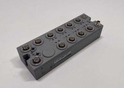
The X20 Compact CPU series is characterized by 3 integrated I/O modules. The device is equipped with 30 different digital inputs/outputs and 2 analog inputs. 1 analog input can be used for PT1000 resistance temperature measurement.
The X20CP1382 is equipped with an Intel x86 400 MHz compatible processor, 256 MB RAM and 2 GB built-in flash drive. The FRAM for storing remanent variables has 32 kB available. A fanless and battery-free design ensures maintenance-free operation.
The CPU is equipped with Ethernet, 2x USB and an RS232 interface. In addition, POWERLINK and CAN bus are available as integrated interfaces. If additional fieldbus connections are needed, the CPU can be upgraded with an interface module from the standard X20 product range.
| Interfaces | 1x RS232, 1x Ethernet, 1x POWERLINK, 2x USB, 1x X2X Link, 1x CAN bus |
| System module | CPU |
| B&R ID code | 0xDABB |
| Cooling | Fanless |
| Status indicators | CPU function, Ethernet, POWERLINK, RS232, CAN bus, CAN bus terminating resistor, CPU power supply, I/O power supply, I/O function per channel |
| Diagnostics | |
| Outputs | Digital outputs: Yes, using LED status indicator and software (output error status) |
| CPU function | Yes, using LED status indicator |
| CAN bus data transfer | Yes, using LED status indicator |
| RS232 data transfer | Yes, using LED status indicator |
| Inputs | Analog inputs: Yes, using LED status indicator and software |
| Ethernet | Yes, using LED status indicator |
| I/O power supply | Yes, using LED status indicator |
| POWERLINK | Yes, using LED status indicator |
| Supply voltage monitoring | Yes, using LED status indicator |
| Temperature | Yes, using software register |
| Terminating resistor | Yes, using LED status indicator |
| Support | |
| Controller redundancy | No |
| ACOPOS support | Yes |
| reACTION-capable I/O channels | No |
| Visual Components support | Yes |
| Power consumption without interface module and USB | 5.5 W |
| Power consumption for X2X Link power supply | 0.8 W |
| Power consumption | |
| Internal I/O | 2.3 W |
| Additional power dissipation caused by actuators (resistive) [W] | - |
| Type of signal lines | Shielded lines must be used for all high-speed digital inputs/outputs, line length: Max. 20 m |
| Certifications | |
| CE | Yes |
| UKCA | Yes |
| ATEX |
Zone
2,
II
3G
Ex
nA
nC
IIA
T5
Gc IP20, Ta (see X20 user's manual) FTZÚ 09 ATEX 0083X |
| UL |
cULus
E115267 Industrial control equipment |
| HazLoc |
cCSAus
244665 Process control equipment for hazardous locations Class I, Division 2, Groups ABCD, T5 |
| DNV |
Temperature:
B(0
-
55°C) Humidity: B(up to 100%) Vibration: B(4 g) EMC: B(bridge and open deck) |
| LR | ENV1 |
| KR | Yes |
| ABS | Yes |
| EAC | Yes |
| Input voltage | 24 VDC -15% / +20% |
| Input current | Max. 1 A |
| Fuse | Integrated, cannot be replaced |
| Reverse polarity protection | Yes |
| Nominal output power | 2 W |
| Parallel connection | Yes |
| Redundant operation | Yes |
| Input voltage | 24 VDC -15% / +20% |
| Fuse | Required line fuse: Max. 10 A, slow-blow |
| Nominal output voltage | 24 VDC |
| Permissible contact load | 10 A |
| Real-time clock | Retention for at least 300 hours, typ. 1000 hours at 25°C, 1 s resolution, -18 to 28 ppm accuracy at 25°C |
| FPU | Yes |
| Processor | |
| Type | Vx86EX |
| Clock frequency | 400 MHz |
| L1 cache | |
| Data code | 16 kB |
| Program code | 16 kB |
| L2 cache | 128 kB |
| Integrated I/O processor | Processes I/O data points in the background |
| Modular interface slots | 1 |
| Remanent variables | 32 kB FRAM, retention >10 years |
| Shortest task class cycle time | 1 ms |
| Typical instruction cycle time | 0.0199 µs |
| Standard memory | |
| RAM | 256 MB DDR3 SDRAM |
| Application memory | |
| Type | 2 GB eMMC flash memory |
| Data retention | 10 years |
| Writable data amount | |
| Guaranteed | 40 TB |
| Results for 5 years | 21.9 GB/day |
| Guaranteed erase/write cycles | 20,000 |
| Error-correcting code (ECC) | Yes |
| Interface IF1 | |
| Signal | RS232 |
| Variant | Connection via 16-pin terminal block X20TB1F |
| Max. distance | 900 m |
| Transfer rate | Max. 115.2 kbit/s |
| Interface IF2 | |
| Signal | Ethernet |
| Variant | 1x RJ45 shielded |
| Line length | Max. 100 m between 2 stations (segment length) |
| Transfer rate | 10/100 Mbit/s |
| Transfer | |
| Physical layer | 10BASE-T/100BASE-TX |
| Half-duplex | Yes |
| Full-duplex | Yes |
| Autonegotiation | Yes |
| Auto-MDI/MDIX | Yes |
| Interface IF3 | |
| Fieldbus | POWERLINK managing or controlled node |
| Type | Type 4 |
| Variant | 1x RJ45 shielded |
| Line length | Max. 100 m between 2 stations (segment length) |
| Transfer rate | 100 Mbit/s |
| Transfer | |
| Physical layer | 100BASE-TX |
| Half-duplex | Yes |
| Full-duplex | POWERLINK mode: No / Ethernet mode: Yes |
| Autonegotiation | Yes |
| Auto-MDI/MDIX | Yes |
| Interface IF4 | |
| Type | USB 1.1/2.0 |
| Variant | Type A |
| Max. output current | 0.5 A |
| Interface IF5 | |
| Type | USB 1.1/2.0 |
| Variant | Type A |
| Max. output current | 0.1 A |
| Interface IF6 | |
| Fieldbus | X2X Link master |
| Interface IF7 | |
| Signal | CAN bus |
| Variant | Connection via 16-pin terminal block X20TB1F |
| Max. distance | 1000 m |
| Transfer rate | Max. 1 Mbit/s |
| Terminating resistor | Integrated in module |
| Controller | SJA 1000 |
| Quantity | 14 standard inputs, 4 high-speed inputs and 4 mixed channels, configuration as input or output using software |
| Nominal voltage | 24 VDC |
| Input voltage | 24 VDC -15% / +20% |
| Input current at 24 VDC |
X1
-
Standard
inputs:
Typ.
3.5
mA X2 - Standard inputs: Typ. 2.68 mA X2 - High-speed inputs: Typ. 3.5 mA X3 - Mixed channels: Typ. 2.68 mA |
| Input circuit | Sink |
| Input filter | |
| Hardware |
Standard
inputs
and
mixed
channels:
≤200
μs High-speed inputs: ≤2 μs, when used as standard inputs: ≤200 μs |
| Software | Default 1 ms, configurable between 0 and 25 ms in 0.1 ms increments |
| Connection type | 1-wire connections |
| Input resistance |
X1
-
Standard
inputs:
6.8
kΩ X2 - Standard inputs: 8.9 kΩ X2 - High-speed inputs: 6.8 kΩ X3 - Mixed channels: 8.9 kΩ |
| Additional functions |
X2
-
High-speed
digital
inputs: 2x 250 kHz event counting, 2x AB counter, ABR incremental encoder, direction/frequency, period measurement, gate measurement, differential time measurement, edge counters, edge times |
| Switching threshold | |
| Low | <5 VDC |
| High | >15 VDC |
| Quantity | 2 |
| Encoder inputs | 24 V, asymmetrical |
| Counter size | 32-bit |
| Input frequency | Max. 100 kHz |
| Evaluation | 4x |
| Encoder power supply | Module-internal, max. 300 mA |
| Overload characteristics of encoder power supply | Short-circuit proof, overload-proof |
| Quantity | 1 |
| Encoder inputs | 24 V, asymmetrical |
| Counter size | 32-bit |
| Input frequency | Max. 100 kHz |
| Evaluation | 4x |
| Encoder power supply | Module-internal, max. 300 mA |
| Overload characteristics of encoder power supply | Short-circuit proof, overload-proof |
| Quantity | 2 |
| Signal form | Square wave pulse |
| Evaluation | 1x |
| Input frequency | Max. 250 kHz |
| Counter frequency | 250 kHz |
| Counter size | 32-bit |
| Possible measurements | Period measurement, gate measurement, differential time measurement, edge counter, edge times |
| Measurements per module | Each function up to 2x |
| Counter size | 32-bit |
| Input frequency | Max. 10 kHz |
| Timestamp | 1 µs resolution |
| Signal form | Square wave pulse |
| Input | ±10 V or 0 to 20 mA / 4 to 20 mA, via different terminal connections |
| Input type | Differential input |
| Digital converter resolution | |
| Voltage | ±12-bit |
| Current | 12-bit |
| Conversion time |
1
channel
enabled:
100
µs 2 channels enabled: 200 µs |
| Output format | |
| Data type | INT |
| Voltage | INT 0x8001 - 0x7FFF / 1 LSB = 0x0008 = 2.441 mV |
| Current | INT 0x0000 - 0x7FFF / 1 LSB = 0x0008 = 4.883 μA |
| Input impedance in signal range | |
| Voltage | 20 MΩ |
| Current | - |
| Load | |
| Voltage | - |
| Current | <300 Ω |
| Input protection | Protection against wiring with supply voltage |
| Permissible input signal | |
| Voltage | Max. ±30 V |
| Current | Max. ±50 mA |
| Output of digital value during overload | Configurable |
| Conversion procedure | SAR |
| Input filter | Third-order low-pass filter / Cutoff frequency 1 kHz |
| Max. error | |
| Voltage | |
| Gain | 0.18% (Rev. <C0: 0.37%) |
| Offset | 0.04% (Rev. <C0: 0.25%) |
| Current | |
| Gain | 0 to 20 mA = 0.15% (Rev. <C0: 0.52%) / 4 to 20 mA = 0.25% |
| Offset | 0 to 20 mA = 0.1% (Rev. <C0: 0.4%) / 4 to 20 mA = 0.15% |
| Max. gain drift | |
| Voltage | 0.017 %/°C |
| Current | 0 to 20 mA = 0.015 %/°C / 4 to 20 mA = 0.023 %/°C |
| Max. offset drift | |
| Voltage | 0.008 %/°C |
| Current | 0 to 20 mA = 0.008 %/°C / 4 to 20 mA = 0.012 %/°C |
| Common-mode rejection | |
| DC | 70 dB |
| 50 Hz | 70 dB |
| Common-mode range | ±12 V |
| Crosstalk between channels | <-70 dB |
| Nonlinearity | |
| Voltage | <0.025% |
| Current | <0.05% |
| Quantity | 1 |
| Input | Resistance measurement with constant current supply for 2-wire connections |
| Digital converter resolution | 13-bit |
| Conversion time |
Only
temperature
input
enabled:
200
µs Temperature and analog input enabled: 400 µs |
| Conversion procedure | SAR |
| Output format | INT or UINT for resistance measurement |
| Sensor | |
| Pt1000 | -200 to 850°C |
| Resistance measurement range | 0.1 to 4000 Ω |
| Temperature sensor resolution | 1 LSB = 0x0005 = 0.16°C |
| Resistance measurement resolution | 1 LSB = 0x0005 = 0.49 Ω |
| Input filter | First-order low-pass filter / cutoff frequency 7 Hz |
| Sensor standard | EN 60751 |
| Common-mode range | 1 V |
| Linearization method | Internal |
| Measurement current | 1 mA |
| Permissible input signal | Short-term max. ±30 V |
| Max. error at 25°C | |
| Gain | 0.3% (Rev. <C0: 1.93%) |
| Offset | 0.15% (Rev. <C0: 0.32%) |
| Max. gain drift | 0.023 %/°C |
| Max. offset drift | 0.012%/°C |
| Nonlinearity | <0.05% |
| Standardized range of values for resistance measurement | 0.1 to 4000.0 Ω |
| Crosstalk between channels | <-70 dB |
| Common-mode rejection | |
| 50 Hz | >60 dB |
| Temperature sensor normalization | |
| Pt1000 | -200 to 850°C |
| Quantity | 4 standard outputs, 4 high-speed outputs and 4 mixed channels, configuration as input or output using software |
| Variant |
Standard
outputs
and
mixed
channels:
Current-sourcing
FET High-speed outputs: Push-Pull |
| Nominal voltage | 24 VDC |
| Switching voltage | 24 VDC -15% / +20% |
| Nominal output current |
Standard
outputs
and
mixed
channels:
0.5
A High-speed outputs: 0.2 A |
| Total nominal current |
Standard
outputs
and
mixed
channels:
4
A High-speed outputs: 0.8 A |
| Connection type | 1-wire connections |
| Output circuit |
Standard
outputs
and
mixed
channels:
Source High-speed outputs: Sink or source |
| Output protection |
Thermal
shutdown
in
the
event
of
overcurrent
or
short
circuit
(see
value
"Short-circuit
peak
current") Internal freewheeling diode for switching inductive loads (see section "Switching inductive loads") |
| Pulse width modulation | |
| Period duration | 5 to 65535 µs corresponds to 200 kHz to 15 Hz |
| Pulse duration | 0 to 100%, minimum 2.5 µs |
| Resolution for pulse duration | 0.1% of the configured frequency |
| Diagnostic status |
Standard
outputs
and
mixed
channels:
Output
monitoring
with
10
ms
delay High-speed outputs: Output monitoring with 10 µs delay |
| Leakage current when the output is switched off |
Standard
outputs
and
mixed
channels:
5
µA High-speed outputs: 25 µA |
| RDS(on) | 140 mΩ |
| Residual voltage |
Standard
outputs
and
mixed
channels:
<0.1
V
at
nominal
current
0.5
A High-speed outputs: <0.9 V at nominal current 0.1 A |
| Peak short-circuit current |
Standard
outputs
and
mixed
channels:
<3
A High-speed outputs: <20 A |
| Switch-on in the event of overload shutdown or short-circuit shutdown |
Standard
outputs
and
mixed
channels:
Approx.
10
ms
(depends
on
module
temperature) High-speed outputs: No switch-on |
| Switching delay | |
| 0 → 1 |
Standard
outputs
and
mixed
channels:
<300
µs High-speed outputs: <3 µs |
| 1 → 0 |
Standard
outputs
and
mixed
channels:
<300
µs High-speed outputs: <3 µs |
| Switching frequency | |
| Resistive load |
Standard
outputs
and
mixed
channels:
Max.
500
Hz High-speed outputs: 50 kHz, max. 200 kHz (see section "Switching frequency derating for high-speed digital outputs") |
| Inductive load | See section "Switching inductive loads". |
| Braking voltage when switching off inductive loads | Standard outputs and mixed channels: Typ. 45 VDC |
| Electrical isolation |
Ethernet
(IF2),
POWERLINK
(IF3)
and
X2X
(IF6)
isolated
from
each
other,
from
other
interfaces
and
from
PLC Channel isolated from bus Channel not isolated from channel or PLC |
| Mounting orientation | |
| Horizontal | Yes |
| Vertical | Yes |
| Installation elevation above sea level | |
| 0 to 2000 m | No limitation |
| >2000 m | Reduction of ambient temperature by 0.5°C per 100 m |
| Degree of protection per EN 60529 | IP20 |
| Temperature | |
| Operation | |
| Horizontal mounting orientation | -25 to 60°C |
| Vertical mounting orientation | -25 to 50°C |
| Derating | See section "Switching frequency derating for high-speed digital outputs". |
| Storage | -40 to 85°C |
| Transport | -40 to 85°C |
| Relative humidity | |
| Operation | 5 to 95%, non-condensing |
| Storage | 5 to 95%, non-condensing |
| Transport | 5 to 95%, non-condensing |
| Note |
X20
end
cover
plate
(right)
included
in
delivery 3 X20 terminal blocks (16-pin) included in delivery Interface module slot cover included in delivery |
| Dimensions | |
| Width | 164 mm |
| Height | 99 mm |
| Depth | 75 mm |
| Weight | 310 g |