English
Sign in
| Price | Negotiable |
| MOQ | 1000PCS |
| Delivery Time | 5-7 days |
| Brand | TIAN RUI |
| Place of Origin | China |
| Certification | ROHS REACH |
| Model Number | 3R-3S |
| Packaging Details | 1000pcs/PE bag |
| Payment Terms | D/P,T/T,Paypal,Western Union |
| Supply Ability | 1000000+PCS+Month |
| Place of Origin | China | Size | 3.5mm*3.5mm*6.8mm |
| Packaging Details | 1000pcs/PE bag | Product Name | 3R-3S Gas Discharge Tubes |
| 8/20μs Impulse Current | 2KA | Tolerance | 30% |
| Electrode Numbers | 3 Electrodes | Model Number | 3R-3S |
| Supply Ability | 1000000+PCS+Month | Lead Type | SMD |
| Certification | ROHS REACH | Weight | 0.3g |
| Brand Name | TIAN RUI | Payment Terms | D/P,T/T,Paypal,Western Union |
| Price | Negotiable | Delivery Time | 5-7 days |
| Minimum Order Quantity | 1000PCS | DC Spark-Over Voltage | 90V-470V |
| Ultra Low Capacitance | Max 1pF | Application | industrial equipment |
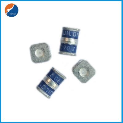
3R-3S Ceramics Surge Protection 3 Electrode Gas Discharge Tubes GDT For High Bandwidth Applications
Description of 3R-3S Ceramics Surge Protection 3 Electrode Gas Discharge Tubes GDT For High Bandwidth Applications
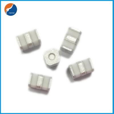
Gas discharge tubes (GDT) use noble gasses enclosed in ceramic tubes to provide an alternate circuit path for voltagespikes. The ceramic envelope and with nickel connectors allow for high loads. 3R-3S Gas Discharge Tubes (GDT) series has a surge rating of 2kA, 8/20μs.Offered in a Squared Surface Mount package, which helps to make pick and place on PCB process easier.
This
GDT
series
is
perfectly
suited
for
broadband
equipment
applications.
The
GDT’s
low
off-state
capacitance
is
compatible
with
high
bandwidth
applications
and
this
capacitance
loading
value
does
not
vary
if
the
voltage
across
the
GDT
changes.
3R-3S
Gas
Discharge
Tube
(GDT)
series
are
specifically
designed
for
protection
of
electrical,
multimedia,
and
communication
equipment
against
over
voltage
transients
in
surface
mount
assembly
applications.


Features of 3R-3S Ceramics Surge Protection 3 Electrode Gas Discharge Tubes GDT For High Bandwidth Applications
•
Extremely
small
size
•
Excellent
response
to
fast
rising
transients
•
Stable
breakdown
voltage
•
GHz
working
frequency
•
8/20μs
Impulse
current
capability:
2KA
•
Surface
Mount
package
•
Non-Radioactive
•
Ultra
Low
capacitance
(<1pF)
•
High
insulation
resistance
•
Lead-free
compliant
•
RoHS
and
REACH
compliant
•
Size:
3.5mm*3.5mm*6.8mm
•
Storage
and
operational
temperature:
-40~+90°C
Applications of 3R-3S Ceramics Surge Protection 3 Electrode Gas Discharge Tubes GDT For High Bandwidth Applications
•
Communication
equipment
•
CATV
equipment
•
Data
lines
•
Telecom
SLIC
protection
•
Broadband
equipment
•
ADSL
equipment,
including
ADSL2+
•
XDSL
equipment
•
Satellite
and
CATV
equipment
•
Test
equipment
•
Consumer
electronics
•
ESD
protection

Electrical Characteristics of 3R-3S Ceramics Surge Protection 3 Electrode Gas Discharge Tubes GDT For High Bandwidth Applications
| Part Number |
DC Spark-over Voltage 1) 2) 3) @100V/S |
Impulse Spark-over Voltage 3) |
Insulation
Resistance 3) 4) |
Capacitance
@1MHz 3) |
Glow
Voltage
@10mA 3) |
Arc
Voltage
@1A 3) |
Life Ratings | ||||||||||||||||||||||||||||
|
Impulse
Discharge
Current @8/20μs 5) |
Impulse
Discharge
Current @8/20μs 6) |
Impulse
Withstanding
Voltage
Capacity
@10/700μS,
40 ±5 times 7) |
|||||||||||||||||||||||||||||||||
| 100V/μS | 1KV/μS | ||||||||||||||||||||||||||||||||||
| Max | Max | Min | Max | Type | Type |
Nominal ±5 times |
Max 1 time | Nominal 300 times | |||||||||||||||||||||||||||
| V | V | V | GΩ | pF | V | V | KA | KA | A | KV | |||||||||||||||||||||||||
| 3R090F-3S | 90±30% | 500 | 600 | 1 | 1 | 60 | 10 | 2 | 3 | 100 | 6 | ||||||||||||||||||||||||
| 3R150F-3S | 150±30% | 500 | 600 | 1 | 1 | 60 | 10 | 2 | 3 | 100 | 6 | ||||||||||||||||||||||||
| 3R200F-3S | 200±30% | 600 | 700 | 1 | 1 | 60 | 10 | 2 | 3 | 100 | 6 | ||||||||||||||||||||||||
| 3R230F-3S | 230±30% | 600 | 700 | 1 | 1 | 60 | 10 | 2 | 3 | 100 | 6 | ||||||||||||||||||||||||
| 3R350F-3S | 350±30% | 800 | 900 | 1 | 1 | 60 | 15 | 2 | 3 | 100 | 6 | ||||||||||||||||||||||||
| 3R400F-3S | 400±30% | 850 | 950 | 1 | 1 | 60 | 15 | 2 | 3 | 100 | 6 | ||||||||||||||||||||||||
| 3R420F-3S | 360-560 | 850 | 950 | 1 | 1 | 60 | 15 | 2 | 3 | 100 | 6 | ||||||||||||||||||||||||
| 3R470F-3S | 470±30% | 900 | 1000 | 1 | 1 | 60 | 15 | 2 | 3 | 100 | 6 | ||||||||||||||||||||||||
| Glow to Arc transition Current…………………………………………................... ~0.3A | |||||||||||||||||||||||||||||||||||
| Weight ~0.30g | |||||||||||||||||||||||||||||||||||
| Operation and storage temperature…………………………………..................... -40~+90°C | |||||||||||||||||||||||||||||||||||
| Climatic category (IEC 60068-1) 40/90/21 | |||||||||||||||||||||||||||||||||||
| Marking………………………………………………………………….................... Without | |||||||||||||||||||||||||||||||||||
| Surface treatment Matte-tin plated | |||||||||||||||||||||||||||||||||||
|
1)
At
delivery
AQL
0.65
level
II,
DIN
ISO
2859 2) In ionized mode 3) Tip or ring electrode to center electrode 4) Insulation Resistance Measuring Voltage: 90V~150V at DC 50V Other at DC 100V 5) Total current through center electrode, half value through tip respectively ring electrode. 6) Tip to ring electrode. 7) Tip to center electrode additional ring to center electrode. Terms in accordance with ITU-T Rec. K.12, IEC 61643-311, GB/T 9043. |
|||||||||||||||||||||||||||||||||||

| Symbol | Millimeters | Inches | |||||||||||||||||||
| A | 3.5±0.2 | 0.138±0.008 | |||||||||||||||||||
| B | 3.5±0.2 | 0.138±0.008 | |||||||||||||||||||
| C | 6.8±0.3 | 0.268±0.012 | |||||||||||||||||||
| D | 1.2±0.3 | 0.047±0.012 | |||||||||||||||||||
| E | 0.4±0.2 | 0.016±0.008 | |||||||||||||||||||
| F | 0.4±0.2 | 0.016±0.008 | |||||||||||||||||||
| X | 1.4 | 0.055 | |||||||||||||||||||
| X1 | 1.8 | 0.071 | |||||||||||||||||||
| X2 | 6.7 | 0.264 | |||||||||||||||||||
| Y | 4.2 | 0.165 | |||||||||||||||||||

| Symbol | Millimeters | Inches | |||||||||||||||||||
| W | 16±0.3 | 0.630±0.012 | |||||||||||||||||||
| A0 | 3.8±0.1 | 0.154±0.004 | |||||||||||||||||||
| B0 | 7.0±0.1 | 0.276±0.004 | |||||||||||||||||||
| K0 | 3.7±0.1 | 0.146±0.004 | |||||||||||||||||||
| P | 8±0.1 | 0.315±0.004 | |||||||||||||||||||
| F | 7.5±0.1 | 0.295±0.004 | |||||||||||||||||||
| E | 1.75±0.1 | 0.069±0.004 | |||||||||||||||||||
| D | 1.5+0.1/-0.0 | 0.059+0.004/-0.0 | |||||||||||||||||||
| P0 | 4±0.1 | 0.157±0.004 | |||||||||||||||||||
| P2 | 2±0.1 | 0.079±0.004 | |||||||||||||||||||
| T | 0.4±0.1 | 0.016±0.004 | |||||||||||||||||||
| D0 | 13.3±0.15 | 0.524±0.006 | |||||||||||||||||||
| D1 | 330±2 | 12.992±0.079 | |||||||||||||||||||
| D2 | 100+1/-2 | 3.937+0.039/-0.079 | |||||||||||||||||||
| W1 | 16.5±0.4 | 0.65±0.016 | |||||||||||||||||||
Soldering Parameters - Reflow Soldering (Surface Mount Devices)

| Reflow Condition | Pb - Free assembly | |||||||||||||||||||||||
| Pre Heat | -Temperature Min (Ts(min)) | 150°C | ||||||||||||||||||||||
| -Temperature Max (Ts(max)) | 200°C | |||||||||||||||||||||||
| - Time (min to max) (ts) | 60 -180 Seconds | |||||||||||||||||||||||
| Average ramp up rate ( Liquids Temp TL) to peak | 3°C/second max | |||||||||||||||||||||||
| TS(max) to TL - Ramp-up Rate | 5°C/second max | |||||||||||||||||||||||
| Reflow | - Temperature (TL) (Liquids) | 217°C | ||||||||||||||||||||||
| - Time (min to max) (ts) | 60 -150 Seconds | |||||||||||||||||||||||
| Peak Temperature (TP) | 260 +0/-5°C | |||||||||||||||||||||||
| Time within 5°C of actual peak Temperature (tp) | 10 - 30 Seconds | |||||||||||||||||||||||
| Ramp-down Rate | 6°C/second max | |||||||||||||||||||||||
| Time 25°C to peak Temperature (TP) | 8 minutes Max | |||||||||||||||||||||||
| Do not exceed | 260°C | |||||||||||||||||||||||